Intro #
This was an internal project that we are sharing for everyone to do if they have the skill to do so. This information is provided as-is with no warranty or support from TH3D. Do this at your own risk.
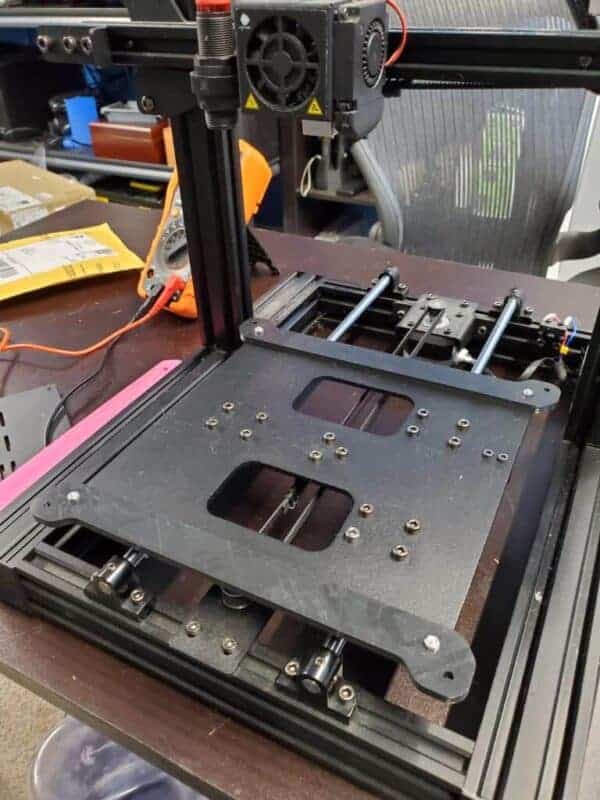
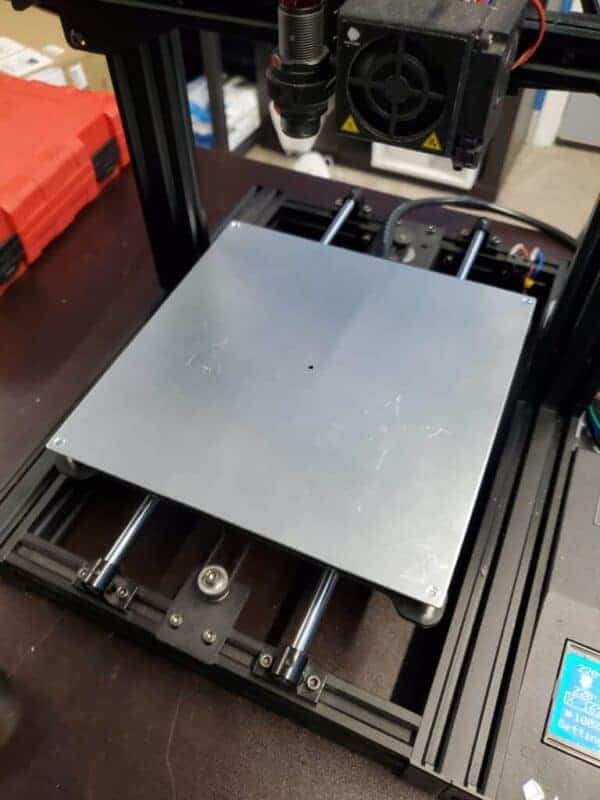
If you want to add a heated bed to your Mega Zero you can do so with the STL file to attach the 220mm 12V heated bed to the machine that is linked below. You will also need a PSU, Cables, MOSFET, and crimp end. Pictures of the installation are attached below with information, but you will need to solder 2 wires to the stock printer board to connect our MOSFET to it.
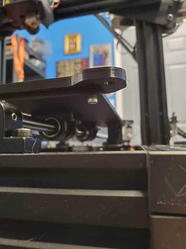
It is HIGHLY recommended to print the bracket in ABS due to the heat it will be near. If you need this printed in ABS you can contact us to get it printed on our ABS farm.
Part & Tool List #
- MOSFET
- MOSFET Bracket (STL in download section) – Use the Generic 2020 One
- M3 Screws and M4 Screws + TNuts Needed
- Heated Bed
- Heated Bed Brackets (2x) (STL in download section)
- PSU
- PSU Cover (STL)
- Crimp Ends
- Crimp Tool
- Wires
- Screw assortment
- Other random parts/supplies to have:
- Heatshrink
- Heat gun
- Solder
- Soldering iron
Downloads #
Installation Pictures and Information #
This information is just being put out there to share with those who want to modify their machine. It is provided as-is and there are many ways to do this upgrade. This is how we did it on our machine here.
This is a fairly complicated installation and is only recommended if you know how to solder and have basic electrical skills.
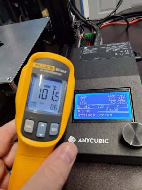
Once this is added you can just flash the printer as the V2 model, which will enable the heated bed control.
Home location is -10 on X and -6 on Y after doing this. Use the HOME_ADJUST option in the firmware to set this so the bed settings are correct.
Powering the Bed and Printer #
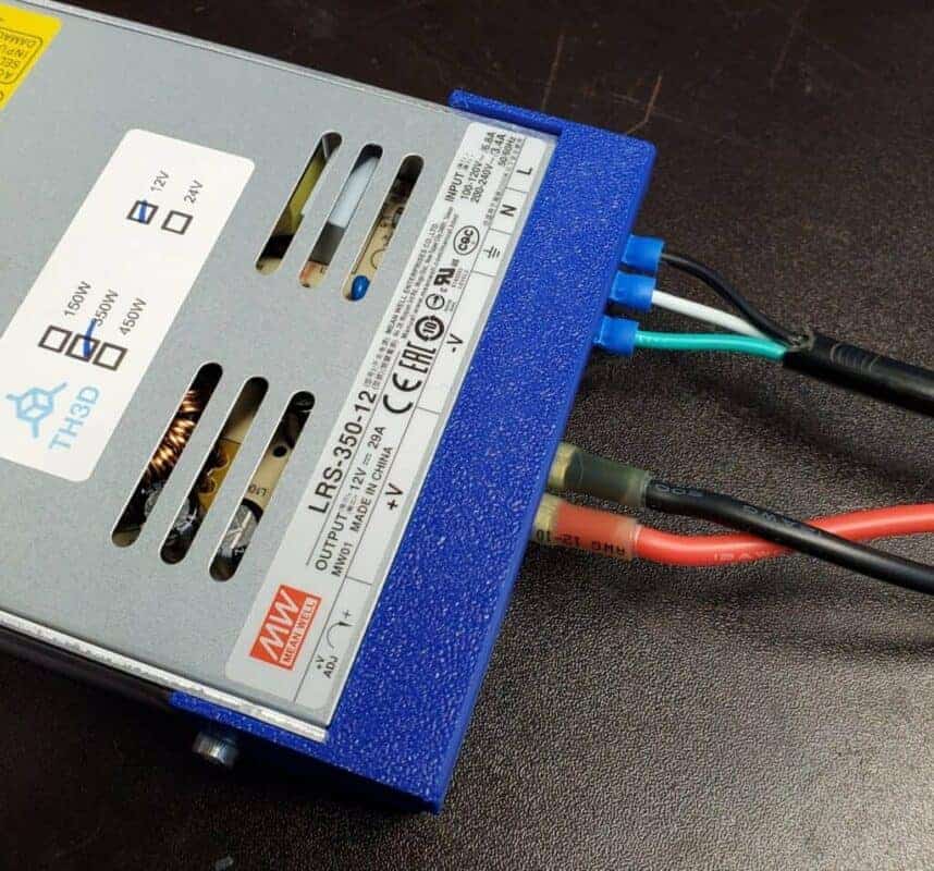
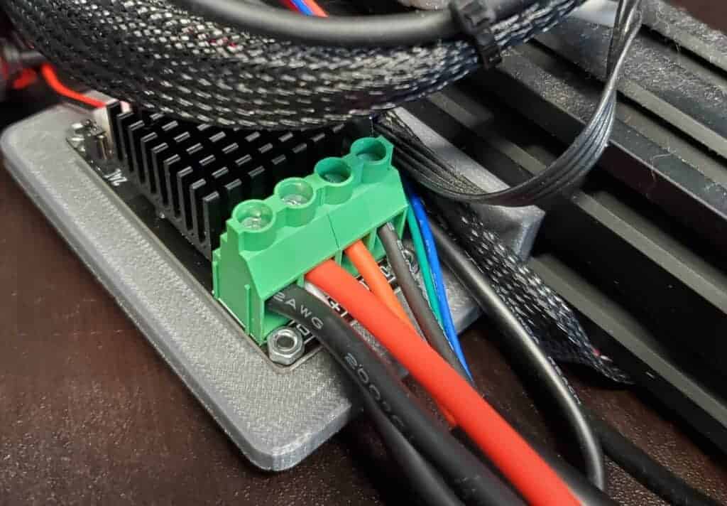
For the AC power cord, we cut the end off the stock one and crimped on blue crimp fork terminals that then go into the Meanwell 350W 12V PSU. For the main power lines, we used our 12 Gauge wire sets and cut them to about 0.5M as we did not need the 1M length for this installation.
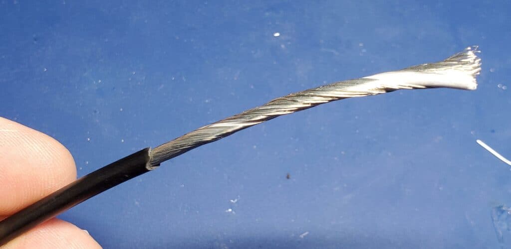
If you opt to use the Meanwell to power everything you can use the stock power cords instead of having to keep running the stock PSU and taking up 2 outlets to power the machine. You can run the board stock off the original PSU but you can run the board AND the heated bed off the 350W 12V Meanwell PSU and that is what we did. We stripped the stock power cord after cutting it from the stock power brick, used heat-shrink on the negative wires (see below for how they look with no shrink) to make them insulated, and then inserted them in with the 12 Gauge wires into the new bed MOSFET power terminal. We used 2x M4x8mm screws to secure the Meanwell PSU printed cover part.

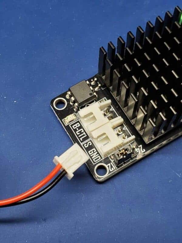
Bed MOSFET Signal Line #
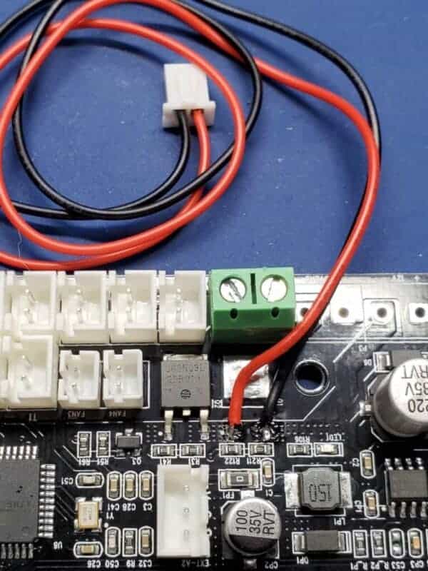
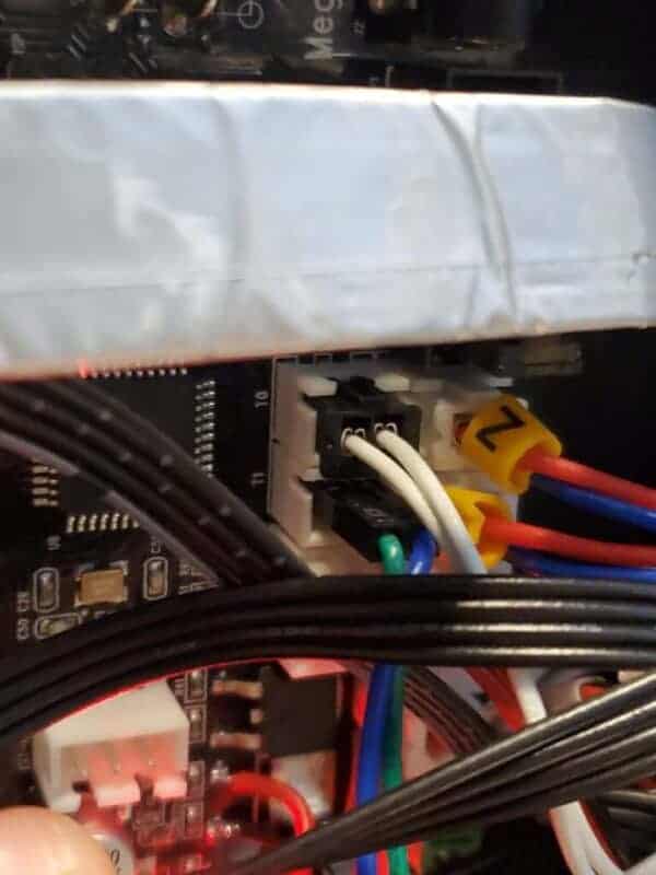
The board does not have a MOSFET populated for the heated bed. But it does have the pads for the control signal. We solder the red/black wires to these pads and they get connected to the S & GND header on our MOSFET. Make sure to get the polarity correct and re-pin the 2 pin JST that comes with our MOSFET before connecting. See the below pictures for soldering examples and the pin setup.
Thermistor connection #
The heated bed thermistor connects to the “T1” header on the board
Final Installation Pictures #